Innovative and Durable Repair Solutions for Concrete Pavement at Hartsfield- Jackson Atlanta International Airport
January 1, 2014Technical Paper
W. Charles Greer, Jr., P.E.
AMEC Environment & Infrastructure, Inc., Alpharetta, GA, USA
Subash Reddy Kuchikulla
Materials Managers and Engineers, Inc., Atlanta, GA, USA
John Rone and James L. Drinkard
Hartsfield-Jackson Atlanta International Airport, Atlanta, GA, USA
ABSTRACT: The busiest airport in the world, Hartsfield-Jackson Atlanta International Airport (ATL), served more than 94 million passengers with over 911,000 aircraft operations in 2013. The planning and execution of maintenance and repair (M&R) activities in an efficient manner with minimal impact on operations is a critical priority. This requires M&R activities that are innovative, executed quickly and effectively during short night time shutdowns yet provide long-lasting durable concrete repairs. This paper focuses on the identification of the distresses, the determination of the type and scope of M&R, and the planning, design, and execution of the activities, the field time for which is often measured in hours and minutes. The ATL M&R Program has two elements: (1) Emergency Repairs and (2) Annual Repairs. Activities are aimed at preserving assets and improving safety. Typical distresses to be repaired include joint seal damage, crack routing and sealing, joint spalls, general pavement spalls, utility conduit spalls, trench drain distress, and full depth slab replacement.
Emergency repairs utilize materials such as methyl methylmethacrylate because asphalt patches usually have to be replaced in less than a year. Emergency repairs are typically performed to reduce foreign object debris potential of a spall and are considered temporary.
The Annual Repair Program is used to promptly address and implement the required repairs that are identified through the annual inspection program. Repairs are typically performed to tight time schedules during relatively short night time closures. Repairs for spalls include a bonding agent, steel tie bars, and steel fiber (more recently polypropylene fiber) reinforced concrete and these have resulted in very good long term performance of the repairs.
KEY WORDS: Concrete, Pavement, Distress, Maintenance, Repair, Materials
1. BACKGROUND
The age of the concrete pavements at ATL range from less than 5 years to more than 40 years. The concrete pavements have typically served well beyond their original design life of 20 years. Runway 9L-27R is one of two main departure runways and the interior 2439 m (8,000 feet) is 40 years old in 2014. The 1984 extensions to this runway are 30 years old in 2014. It has served an estimated 8 million departures. Runway 8L-26R, a main landing runway, is also 30 years old in 2014.
2. ANNUAL REPAIR PROGRAM
The Annual Repair Program is used to identify and establish the extent of on-going M&R to be accomplished each year. Prior to 2007, a repair program was executed every 2 to 3 years. Starting in 2007, the program became the Annual Repair Program. M&R accomplished under this program has increased from 2 million dollars (US) per year in the beginning to approximately 4 million dollars (US) in the current year. The replacement value of the concrete pavement at ATL is estimated to be approximately 2 billion dollars (US). The Annual Repair Program represents a mere 0.1 to 0.2 percent of the replacement value. The program is generally focused on the following types of repairs: joint sealing, crack routing and sealing, spalls, utility conduit spalls, trench drains, and full depth slab replacement. Typical examples of these distresses at ATL are shown in Figures 1 and 2. The repairs made under the Annual Repair Program are intended to be long lasting and permanent.
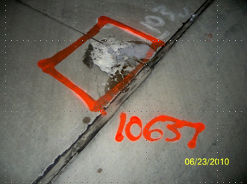
Figure 1: Typical spall distress.
The location and extent of each individual distress is determined by a walking visual inspection process. Inspection is performed for the runways and taxiways all of which are concrete and cover approximately 2.1 million square meters (23 million square feet, more than 500 acres). The inspection of the runways and taxiways requires approximately 16 to 18 nights with approximately 120,000 square meters (1.3 million square feet, 30 acres) inspected each night.
When a spall distress is observed during the inspection program the area is sounded with a steel dowel bar to establish the lateral extent of the area of loose or delaminated concrete. The perimeter is marked with bright orange or yellow paint and the severity is classified subjectively as low, medium, or high. The location is surveyed with a Global Positioning (GPS) unit in a mode capable of plus or minus 30 cm (12 inches) or less. The vertices of the spall are surveyed starting at the southwest vertex and proceeding counterclockwise. Each vertex has a number assigned in the database when it is entered in the GPS unit. One of these numbers is assigned as the distress number for the spall in the database and it is painted on the pavement surface.
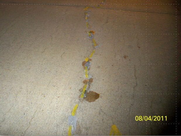
Figure 2: Typical crack routing and sealing distress.
For cracks and joint seal damage, the endpoints of the crack or damaged/missing joint seal are surveyed with the GPS. The vertices of abrupt changes in direction are also surveyed and recorded for the distress. The cracks and missing joint seal distresses are not numbered due to time constraints.
The most common distress in terms of frequency is spalling along longitudinal or transverse joints. These are typically due to failure of the female side of keyways in the longitudinal joints or failure to maintain proper separation across a joint when previous spalls were repaired as shown in Figure 3. Keyways have not been used in pavements constructed at ATL since the early 1980’s (Greer, Kuchikulla, Masters and Rone, 2013). The spall may also be an area where a previous patch has come loose or delaminated.
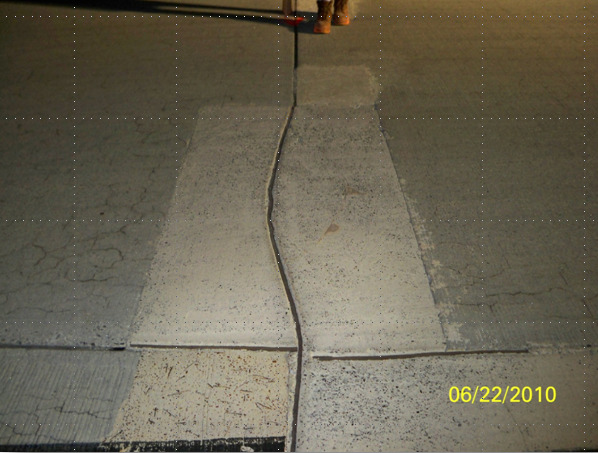
Figure 3: Failure to maintain proper joint alignment and continuity — future distress.
Joint seal damage has generally been the result of failure of the bond between the sealant material and the adjacent concrete to which it was bonded. This has been attributed to failure to properly clean and/or dry the concrete surface prior to placement of the sealant material.
3. STANDARD REPAIR CONCEPTS
A key factor in the establishment of durable PCC repairs at ATL has been the development of standard repair concepts followed by implementation of these concepts in the design of the repairs. Patching of spalls is one of the most common repairs at ATL. For over 25 years, the concept for repair of spalls has involved removal of the distressed concrete down to sound concrete that is relatively level with planar sides through sawing, bush hammering and cleaning of the exposed surface. Vertical holes are drilled into the bottom of the area to be patched along the sides where the adjacent joints are located. The holes are maintained at least 5 cm (2 inches) from the edge of the joint. No. 4 (13 mm or 1/2 inch) reinforcing steel bars are then epoxied in the holes. Holes are drilled in the exposed sides opposite the joint sides of the patch area in a downward direction at approximately 45o with the horizontal. No. 4 bars with a 45o bend are then epoxied in the holes. The bent bars are not installed across the joints so that proper joint movement can still occur.
A horizontal reinforcing steel mat of No. 4 bars, with a variable spacing each way, is then placed so that a cover of 40 mm (1.5 inches) over the steel can be maintained. A tolerance of 13 mm (1/2 inch) is allowed for the cover of the steel mat. The variable spacing for the bars in the steel mat is a minimum of 15 cm (6 inches) to a maximum spacing of 30 cm (12 inches) on center. The steel generally provides a tensile attachment of the patch to the sound concrete that far exceeds the tensile capacity of the sound concrete. The steel also provides integrity to the patch should cracks develop in the replacement concrete. Fiberboard 13 mm (1/2 inch) thick is used at the faces of adjacent slabs in order to maintain a proper joint separation between the repair concrete and the concrete in the adjacent slabs. Figure 4 shows a schematic for a spall repair patch adjacent to 2 joints. Figure 5 shows an actual repair adjacent to 2 joints ready to receive replacement concrete.
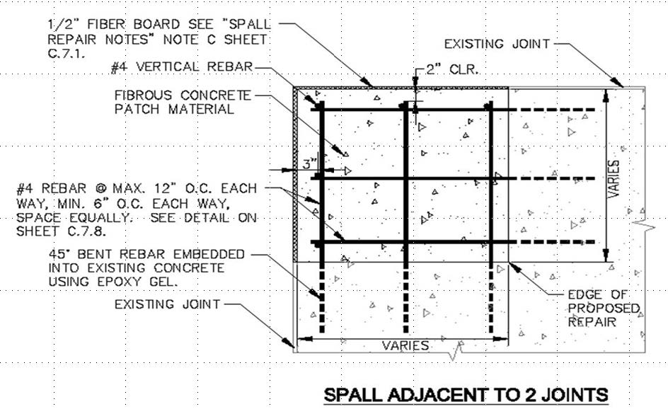
Figure 4: Schematic drawing for spall repair.
A neat cement grout made with high early strength cement is placed on the exposed concrete immediately prior to placement of the replacement concrete. The replacement concrete contains high early strength cement at the rate of 534 kg per cubic meter (900 lbs per cubic yard). The aggregate is a single size No. 7 (ASTM C 33), 19 mm (3/4 inch). The mix also contains polymer fibers (steel fibers were used until the recent past) to provide additional integrity to the patch should any cracks develop in the patch concrete. The flexural strength is specified to be 3105 kPa (450 psi) at 4 hours and 4830 kPa (700 psi) at 24 hours. The patch operation is scheduled at night and in a timeframe such that the patch can cure for 4 hours before opening to traffic. Patches made in this manner have served and are still serving well under traffic after more than 20 years. The joint sealant is placed once the all the repairs have been made so that the contractor only has to mobilize once.
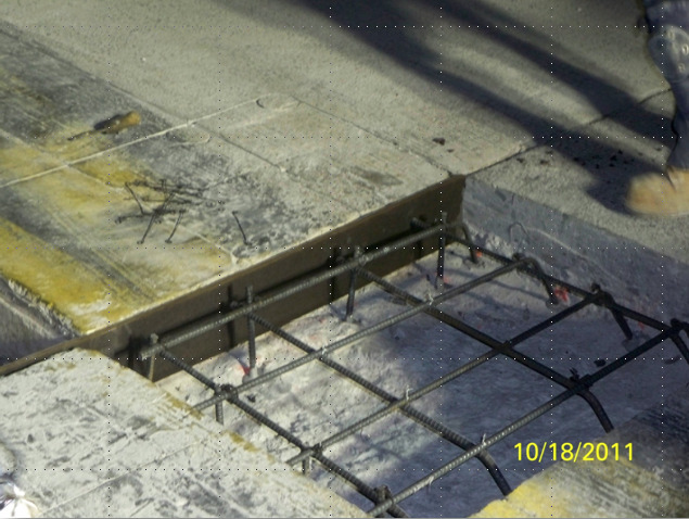
Figure 5: Spall repair showing reinforcing and tie bars to sound concrete below.
Another common repair is sealing of cracks in the surface of the PCC slabs. This is accomplished by routing the crack out to a width of 9 mm (3/8 inch). The routed crack is then sandblasted and cleaned by blowing debris out of the routed crack with an air wand. A backer rod is then inserted in the routed crack followed by installation of the sealant. The sealant material used is Dow 888 or approved equivalent.
4. CASE HISTORY – CONCRETE PAVEMENT DISTRESS AND REPAIR FOR TAXIWAY E
Over the years there have been some very interesting case histories regarding distress, investigation, evaluation, and repair at ATL. These have involved issues within the pavement layers and outside the pavement layers.
4.1 Taxiway E – Corner Cracking – Background
One of the more interesting and unique distresses observed at ATL was an issue involving corner cracking of the concrete slabs in Taxiway E. The corner cracking distress occurred along a portion of the taxiway for a distance of approximately 462 m (1500 feet). Over the last 40 years, this location and another section further to the east on Taxiway E have been the only places where this distress has been observed. The location further to the east was observed some years subsequent to the location discussed in this section of this paper. The taxiway was constructed as part of the midfield expansion for the Central Terminal Passenger Complex (CTPC) in the late 1970’s. The taxiway serves primarily outbound aircraft departures. The pavement consisted of 40 cm (16 inches) of plain Portland cement concrete (PCC) over 15 cm (6 inches) of cement treated base (CTB) over 15 cm (6 inches) of soil-cement (SC) over prepared subgrade. The specified 28 day flexural strength (third-point loading) for the PCC was 4480 kPa (650 psi). The 7 day compressive strengths for the CTB and SC were 5170 kPa (750 psi) and 2760 kPa (400 psi), respectively.
The PCC pavement consisted of three lanes 7.6 m (25 feet) wide placed with slipform paving techniques. Transverse joints were sawed at a spacing of 7.6 m (25 feet) longitudinally. The transverse joints were doweled with 38 mm (1-1/2 inch) diameter by 50 cm (20 inches) long steel dowels that were set in dowel baskets prior to placement of the concrete. The longitudinal joints were keyed and tied with deformed reinforcing bars 13 mm (1/2 inch) in diameter. The three lane configuration placed the longitudinal joints such that the main gears of the large commercial aircraft traversed on or very near the longitudinal joints. A visual inspection of the distress in Taxiway E was performed on February 20, 1987. Figure 6 shows a typical corner crack observed in the taxiway. There was also differential in the elevation of the top of the slabs across the transverse joint of approximately 3 to 6 mm (1/8 to 1/4 inch). This occurred even though the transverse joint was doweled as described previously.
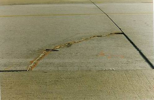
Figure 6: Typical corner crack distress in Taxiway E.
During the visual inspection, a DC-8 aircraft that had just landed was taxied along the taxiway in the area of distress. The corner of one slab in the middle lane of pavement was observed to deflect visibly from a distance of approximately 7.6 m (25 feet) as one of the gears of the aircraft traversed the slab at the corner. The corner of the PCC slab that was observed to deflect was not yet cracked. This slab was designated as Slab 37B.
4.2 Engineering Investigation – Field
An engineering investigation consisting of coring of the PCC, CTB and SC along with conventional soil test borings with split spoon sampling (ASTM D 1586) to depths up to 5 to 21 m (16.5 to 68.5 feet) at 16 locations along the area of distress was performed. Undisturbed sampling (ASTM D 1587) of the subgrade soil was performed at periodic depths in the borings. The cores of PCC were 15 cm (6 inches) in diameter. The cores of CTB and SC were 10 cm (4 inches) in diameter.
One coring/boring was located in the deflecting corner of Slab 37B approximately 1.2 m (4 feet) from the corner along the diagonal of the slab. A void approximately 3 to 6 mm (1/8 to 1/4 inch) thick was encountered beneath the PCC and the top of CTB as shown in Figure 7. Voids ranging from 3 to 6 mm (1/8 to 1/4 inch) between the PCC and the CTB were encountered in 9 of the remaining 15 corings/borings.
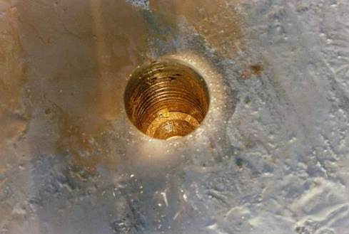
Figure 7: Void between PCC and CTB in the coring/boring in Slab 37B in Taxiway E.
4.3 Engineering Investigation – Falling Weight Deflectometer
ATL has had a Pavement Management Program in place since 1984 that involves extensive testing with falling weight deflectometer (FWD) technology along with many other techniques. This program has been reported elsewhere in detail (Greer, Kuchikulla, and Drinkard, 2012). The 1987 program was performed in the January to February timeframe and the data were available for use in the evaluation of the taxiway. The FWD data included stiffness data for the center of slabs, the longitudinal joint near the mid-length of slabs, the transverse joint near the mid-width of slabs and the corners of slabs. Deflection based joint efficiencies across joints were determined for these joint locations. The joint efficiencies for the corner slabs were measured across the transverse joints at the corners.
4.4 Engineering Investigation – Laboratory
In the laboratory, the cores of PCC were cut near the mid-depth to establish a top and bottom portion for each core location in order to provide samples with length to diameter ratios in the range of 1.3 to 1. The ultrasonic pulse velocity (ASTM C 597) of the PCC cores was determined for the top and bottom portion of each core along the longitudinal axis of each core. The cores of PCC at 12 of the locations were subjected to split tensile tests (ASTM C 496) on the top and bottom portions of the cores. The compressive modulus of elasticity was determined on the top and bottom portions of the PCC cores from the remaining 4 locations (ASTM C 469). These cores were then subjected to compressive strength tests (ASTM C 39). All of the PCC cores were soaked for at least 40 hours in saturated limewater prior to the strength and modulus tests. The cores of CTB and SC that were testable were subjected to compressive strength tests after soaking for 40 hours in saturated limewater. Stress-strain data were collected during the compressive strength tests for the CTB and SC to allow calculation of the modulus of elasticity.
4.5 Engineering Investigation – Results
The results of the engineering investigation are summarized in the following paragraphs. The cores indicated voids 3 to 6 mm (1/8 to 1/4 inch) thick between the bottom of the PCC and the top of the CTB in 10 of the 16 cores. The soil test boring data did not indicate the likelihood of any unusual settlement or weakness of the subgrade soils. The standard penetration resistance values (ASTM D 1586) were typically 0.33 to 0.66 blows per cm (10 to 20 blows per foot). These values are typical for good subgrade soils at ATL. The strength tests on the cores of PCC, CTB, and SC indicated reasonable compliance with the specifications that were used for the original construction. Thus, it was concluded that the pavement support layers were of the quality expected for good support of the PCC and the voids and cracking were due to some other reason.
The FWD data indicated deflection based joint efficiencies across the transverse joints in the area of distress that ranged from 30 to 60 percent with an average of approximately 55 percent. The average longitudinal joint efficiency in the distressed area of the taxiway was approximately 50 percent. The average corner joint efficiency across transverse joints in the area of distress was approximately 34 percent. These values were significantly lower than typical joint efficiencies that were measured in other similar design pavements at ATL during the 1984 testing which was performed in the summer. It should be noted that the transverse joints for transverse and corner joint testing were dowelled.
4.6 Engineering Investigation – Additional Field and Laboratory Testing
In order to further investigate the issue of the deflecting but un-cracked slab, a large diameter core (LDC) was obtained at the corner of Slab 37B and included the corner of each of the other three slabs at the intersection of the transverse and longitudinal joint as shown in Figure 8. A void was expected between the PCC and CTB based on the coring and the visual observations during the passage of the DC-8 as discussed previously. The void and joints were “locked” in place by removing the joint sealant material in the area of the LDC and pouring epoxy into the transverse and longitudinal joints under gravity flow prior to the coring operation. The epoxy was fluid such that it could flow into the void between the PCC and the CTB. The epoxy was allowed to set for one day and the LDC was then cut with a 66 cm (26 inch) diameter diamond tipped rock core bit as shown in Figure 9.
The purpose of the LDC was to expose the area surrounding the interface between the PCC and the underlying CTB at the void without damage from crushing or demolition. The core was extended a short distance into the top of the CTB with the expectation that some of the CTB would be attached to the bottom of the core due to the epoxy. The core was carefully lifted out with an end loader and the hole was inspected and documented with photographs, two of which are shown in Figures 10 and 11.
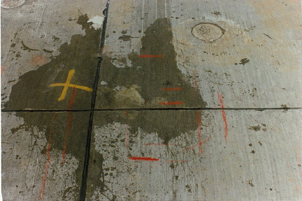
Figure 8: Epoxy used to lock void in place at LDC location (37B).
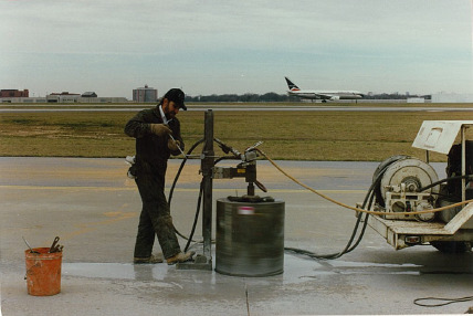
Figure 9: Coring operation for LDC.

Figure 10: Void between bottom of PCC and CTB in LDC — void is 19 mm (3/4 inch).

Figure 11: “Sympathetic” crack in CTB below transverse joint crack in PCC in the LDC.
The following items of interest were observed in the hole left by the removal of the LDC:
- There was a void between the PCC and CTB approximately 3 to 19 mm (1/8 to 3/4 inch) thick near the intersection of the transverse and longitudinal joint (see Figure 10. This was significantly greater than the 3 to 6 mm (1/8 to 1/4 inch) void at the coring/boring location that was approximately 1.2 m (4 feet) from the intersection of the transverse and longitudinal joints along the diagonal of the slab. This indicates that the thickness of the void increased with decreased distance from the intersection. The void also existed beneath Slab 36B on the other side of the transverse joint. The slabs were curled upward at the corners.
- The cracked portion of the transverse joint below the saw cut exhibited an opening of approximately 3 mm (1/8 inch) in the “joint”.
- There was a “sympathetic” crack in the CTB beneath the cracked portion of the PCC below transverse joint saw cut as shown in Figure 11. This indicates that the CTB likely cracked when the concrete above it cracked below the transverse joint saw cut.
- The surface of the PCC across the transverse joint in the LDC was offset vertically by approximately 3 mm (1/8 inch) even though the transverse joint within the LDC had 2 dowels contained in it.
The LDC was returned to the laboratory where it was sawed such that an approximately 10 cm (4 inch) wide vertical slice (top to bottom) could be obtained. The slice was positioned so that the dowel nearest the corner in Slab 37B was contained near the mid-width of the slice. Figure 12 shows the sawing equipment set-up on top of the LDC. Figure 13 shows the slice after sawing.
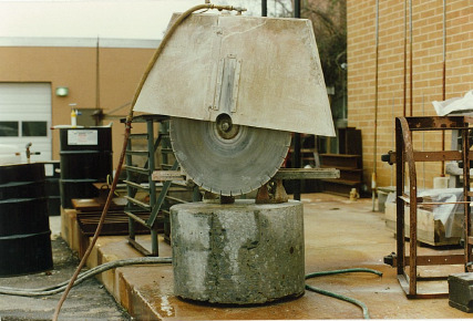
Figure 12: Set-up for sawing of LDC at laboratory.
The slice of the LDC was then x-rayed perpendicular to the side (i.e. parallel to the transverse joint) so the dowel could be observed in the x-ray film. This required several attempts in order to achieve an exposure time that did not “burn” the film and resulted in an acceptable image of the dowel across the transverse joint. Figure 14 shows the resulting xray with the image of the dowel and the surrounding concrete along with a portion of the dowel basket used to hold the dowel during the slipform paving process.

Figure 13: Slice of LDC with embedded dowel bar.
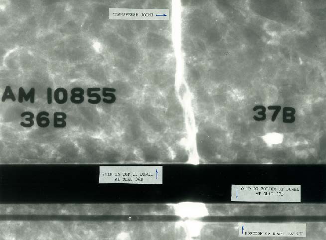
Figure 14: X-ray image of slice from LDC with embedded dowel bar.
The following items of interest were noted in the x-ray image:
- There was a small void on the top of the dowel on the “upstream” side (Slab 36B) of the transverse joint and small void on the bottom of the dowel on the “downstream” side (Slab 37B) of the transverse joint as shown in Figure 14. An examination of the void around the dowel indicated that the dowel was likely cast with a small void around it rather than the small void being the result of “wearing” of the dowel in the dowel hole. The cause of the small void around the dowel could not be determined with certainty. However, it could be the result of a slight amount of excess oil on the dowel at the time of construction or possibly due to a small shift in the position of the dowel while the concrete was still in a plastic state.
- The granitic gneiss large aggregate shown in Figure 15 indicates a vertical offset of 3 mm (1/8 inch) across the crack in the aggregate at the cracked portion of the transverse joint below the saw cut. This vertical offset matches that observed across the transverse joint at the top of the core.
- There was a layer of epoxy approximately 3 to 6 mm (1/8 to 1/4 inch) thick between the bottom of the PCC and the top of CTB. This was the epoxy that was poured into the joint under gravity flow to “lock” the joints and void in position before the coring operation.
- A styrofoam coffee cup was found cast into the concrete at the bottom of the PCC in the LDC. It was the opinion of the investigators that this did not have any effect on the issue of curling or cracking.
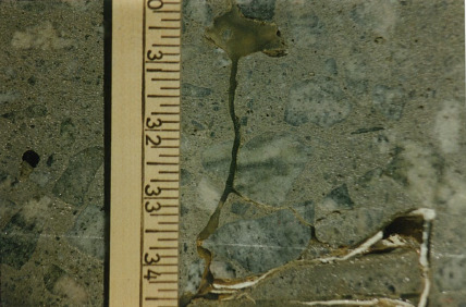
Figure 15: Note the vertical offset of 3 mm (1/8 inch) in the large aggregate. The styrofoam coffee cup (white material) was determined to be of no influence.
It was concluded that many of the PCC slabs in Taxiway E in the area of distress had curled and separated from the CTB. The void between the bottom of the PCC and the top of the CTB appeared to increase as distance to the intersection of the transverse and longitudinal joint decreased. The lateral extent of curling exceeded 1.2 m (4 feet) from the corner as measured along the diagonal of the slabs. The amount of vertical curl at the corner was as much as 19 mm (3/4 inch) as measured in the hole after removal of the LDC.
The corners of the slabs were eventually cracking in fatigue under the repeated loads of the large commercial aircraft main gears that tracked at or very near the longitudinal and corner joints. The curling was attributed to drying shrinkage and/or temperature differentials between the top and bottom of the PCC slabs.
4.7 Taxiway E Repair Plan
The repair plan was established as follows:
- Saw cut the outer lanes of the PCC slabs longitudinally at a distance of 3.5 m (11.5 feet) from the longitudinal joint between the outer lanes and the adjacent middle lane of PCC slabs. The saw cut was to be made full-depth through the PCC, CTB, and into the top 76 mm (3 inches) of the SC.
- An additional saw cut was to be made in the outer lanes of the PCC slabs longitudinally at a distance of 3.8 m (12.5 feet) from the longitudinal joint between the outer lanes and the adjacent middle lane of PCC slabs. The saw cut was to be made full-depth through the PCC and CTB. The intent of this cut was to provide a “buffer” zone, 30 cm (12 inches) wide, to allow demolition and removal of PCC and CTB without damage to the pavement that was to remain in place after the repair.
- Demolish and remove the middle lane and the “interior” portion of outer lanes of the PCC slabs and underlying CTB and SC.
- Remove the remaining 30 cm (12 inch) wide buffer zone strip of PCC at the outer edge of the “interior” portion of outer lanes of the PCC slabs along with the underlying CTB and SC.
- Construct 20 cm (8 inches) of CTB on top of the exposed subgrade.
- Place 56 cm (22 inches) of PCC in two lanes, each 7.6 m (25 feet) wide. This configuration would put the main gears of large commercial aircraft in the middle portions of the new PCC slabs.
- Saw cut transverse joints in the new PCC at a longitudinal spacing of 7.6 m (25 feet).
- Seal the transverse and longitudinal joints and open to traffic.
The repair was accomplished during the summer and fall of 1987.
4.8 Taxiway E Repair Execution – A Repair Issue with the Construction of the Repair
One major issue arose during the construction for the repair. The contractor chose to demolish the PCC with a “headache ball” process. The contractor sawed the in-place outer lanes of PCC slabs at the specified 3.5 m (11.5 feet) and 3.8 m (12.5 feet) distances from the longitudinal joint with the adjacent middle lane of PCC slabs. He then dropped the headache ball on the surface of the PCC slabs to be removed to crush them. The headache ball was “x-shaped”, weighed 5543 kg (12,000 pounds), and was dropped from a height of 1.8 to 2.4 m (6 to 8 feet) above the surface of the PCC. In general, 5 drops were made in an area approximately 60 cm (2 feet) in diameter before the weight was moved to a “new location”. The contractor attempted to keep the headache ball at least 38 cm (15 inches) away from the first longitudinal saw cut on each side of the removal area.
When the contractor removed the crushed PCC from between the two interior saw cuts, portions of the underneath side of the PCC slabs in the buffer zone were observed to have cracked, sheared, and broken. The cracked, sheared, and broken zone was evident in the bottom half of the PCC in the face of the 30 cm (12 inches) buffer zone strip of PCC. The shear was triangular in nature in a direction perpendicular to the face, the thickness decreased with increased depth into the face. The thickness of the shear break was typically in the range of 10 to 20 cm (4 to 8 inches) at the exposed face of the PCC and feathered out at 30 to 45 cm (12 to 18 inches) into the PCC. This indicated that the broken zone could extend as much as 15 cm (6 inches) into the PCC that was to remain in place after removal of the buffer zone. Figures 16 and 17 illustrate the cracked and sheared zone in the face of the PCC and the lateral extent into the PCC.
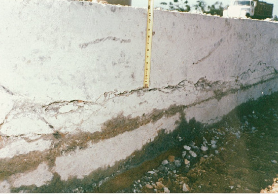
Figure 16: Typical cracked and sheared zone in saw cut face of PCC slab.
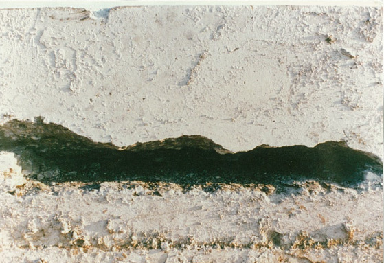
Figure 17: Cracked and sheared zone with pieces removed (Note depth into the PCC).
It was concluded that the headache ball was dropped too close to the saw cut and the crushed concrete was “bulking outward” against the vertical cut face of the buffer zone and the buffer zone concrete was applying a downward force on the face of the PCC that was to remain in place. This was supported by the fact that the outer second saw cut was that was observed to be closed; thereby indicating the buffer zone had moved outward. The downward shear forces were breaking or shearing the bottom of the buffer zone and the PCC slabs that were to remain in place. None of the cracking observed during the construction was encountered during the Engineering Investigation prior to the repair construction activities. Vibration monitoring was also performed during drops of the headache ball and indicated that the vibration velocities during the dropping of the headache ball were not high enough to cause cracking due to vibration.
The solution was to make a third longitudinal saw cut that was an additional 30 cm (12 inches) laterally beyond the buffer zone. This additional section of PCC was removed and this contained the sheared or broken zone at the bottom of the slabs. The contact location of the headache ball was also kept at least 1.8 m (6 feet) away from the additional longitudinal saw cut for the slab removal. The additional saw cut resulted in replacement slabs that were 7.9 m (26 feet) wide. No additional cracked or sheared zones were encountered after the change.
An interesting issue was noticed during the field inspection for the shear issue. The cracked portions below the saw cut for the transverse joints were closed so tight, that the only way to locate the cracked portions of the transverse joints was by looking below the bottom of the saw cuts for the transverse joints. The transverse joint at the LDC location exhibited a width in the cracked zone of approximately 3 mm (1/8 inch) during the February (winter) coring process. The other transverse joints exhibited crack widths that were hairline during the repair program that occurred in summer. This confirmed that thermal expansion of the PCC slabs had occurred with the heat of summer.
The replacement concrete pavement was still in place and serving well during the 2010 Pavement Management Program evaluation. The concrete was 23 years old and exhibited an average Pavement Condition Index of 69. The pavement continues to serve well and will be evaluated again as part of the 2014 Pavement Management Program evaluation. It is currently 27 years old.
5. CASE HISTORY – TAXIWAY D AND L INTERSECTION – UTILITY SLAB DISTRESS REPAIR
Sometimes repairs become necessary due to problems with previous construction or repair activities. One such case is illustrated in the following case history.
5.1 Taxiway D and L Utility Slab Distress – Background
During the Annual Inspection Program as well as more frequent routine general observations, significant distress was first noted around a Utility Slab in the intersection area of Taxiway D and Taxiway L in 2010. The initial distress at this location consisted of localized small spalls that had been repaired previously with routine procedures. These included sealing cracks and patching spalls in six slabs around a heavily reinforced utility slab associated with a manhole and underground drainage lines. The utility slab also had patches in it. The manhole was approximately 1.8 m (6 feet) in diameter and had an invert approximately 4.3 m (14 feet) below the pavement surface. The manhole structure served three incoming drainage pipes and one outgoing drainage pipe that were near the invert of the manhole structure. The incoming pipes included two reinforced concrete drainage pipes (RCP) approximately 40 cm (16 inches) in diameter and a corrugated metal pipe (CMP) approximately 61 cm (24 inches) in diameter. Monitoring over time indicated the need for additional spall repairs. Also, the observations indicated the initiation of cracks within the slabs in the area and indications of shallow depression of the pavement surface. The affected area encompassed 7 slabs that were each 7.6 m (25 feet) by 7.6 m (25 feet). Figure 18 shows the area of concern on June 11, 2010. The depth of the depression was not determined but was visible to the unaided eye.
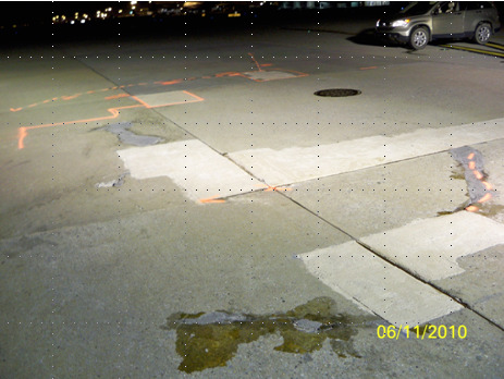
Figure 18: General view of Utility Slab and distressed area in Taxiway D and L on June 11, 2010.
5.2 Engineering Investigation – Taxiway D and L
The distress continued to worsen and in late 2011, it was decided that the area needed to be investigated so a repair could be developed. In order to assess the situation, 2 locations were selected for coring of the PCC, CTB, and SC along with conventional soil test borings to depths of 7.6 m (25 feet) beneath the surface of the PCC. These were located just outside the general depressed area and were performed on November 8, 2011. The soil borings indicated high moisture contents in the subgrade soil. The same night a very limited closed circuit television (CCTV) recording was made of the 2 RCP and the CMP that entered the manhole. The CCTV information revealed an obstruction in the CMP approximately 1.2 m (4 feet) from the manhole. The blockage was thought to be a soil mass and water was observed dripping from the crown of the CMP. It was determined that the CMP was supposed to have been plugged and abandoned some years previous.
On November 18, 2011, three cores of the PCC were obtained in the area of depression. At one location, when the PCC was finally penetrated, the 46 cm (18 inches) long concrete core dropped out of the core barrel and onto its side at the bottom of a void at the bottom of the PCC. No CTB or SC was found beneath the PCC. The void was determined to have a depth of 63 cm (25 inches). Figure 19 shows the core laying on its side in the void. One of the other cores indicated a void beneath the SC. No void was found at the third core location.
The RCP exiting the manhole structure was examined with CCTV techniques that night. Nothing unusual was observed in the outgoing RCP.
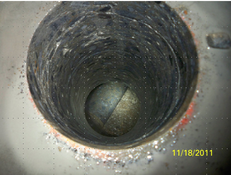
Figure 19: Core, 46 cm (18 inches) long, lying on its side at bottom of void beneath the PCC.
Four additional cores were obtained in December 2011 to further delineate the lateral extent of the void. These were located approximately 7.6 m (25 feet) away from the manhole and they encountered no voids or distress. Based on the results of the cores and soil test borings and the fact that an abandoned CMP drain line exhibited an apparent soil blockage very near the manhole structure, it was assumed that the void beneath the PCC was likely due to a loss of subgrade soil into the abandoned CMP drain line.
5.3 Taxiway D and L Preliminary Repair Plan
Sometimes the engineering investigation does not provide a conclusive answer or operational constraints may dictate that repair plans be developed as you move forward. Since the engineering investigation provided a likely but not completely conclusive cause of the distress it was decided to develop and implement a preliminary design and repair which would include further investigation and confirmation of the cause. Therefore, the preliminary design repair was determined to consist of demolition and removal of the existing PCC, CTB, and SC in the 6 slabs plus the heavily reinforced utility slab. The subgrade soil was to then be excavated to a depth sufficient to expose the abandoned CMP drain line. The excavation revealed that the top of the CMP was near the top of one of the RCPs and very near to it. It also indicated that the CMP was approximately 1.5 m (5 feet) long and had not been properly plugged previously. Soil was being lost into the CMP and likely washed away in the pipe that exited the manhole.
Figure 20 shows the void beneath the SC and CTB. The PCC has been removed from the top of the CTB. Figure 21 shows the CMP drain line and the void where soil was being lost into an opening in the CMP that had not been properly plugged.
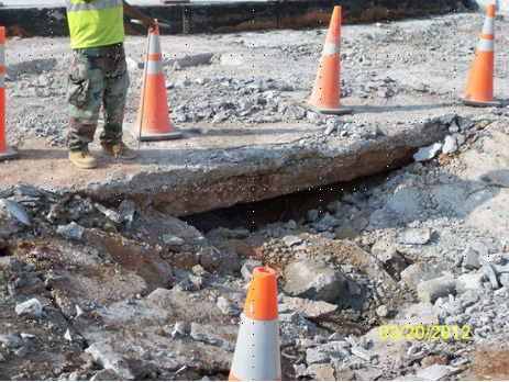
Figure 20: View of void beneath SC and CTB observed during the demolition in the preliminary repair procedures (PCC has been removed).
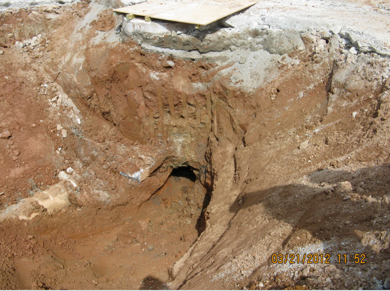
Figure 21: Void and loss of soil in opening in improperly plugged abandoned CMP drain line.
5.4 Taxiway D and L Final Repair and Implementation
Based on the results of the preliminary repair plan and excavation, the final repair consisted of properly plugging the hole in the manhole structure where the CMP entered. The outside of the plug was filled with the placement of approximately 76 cm (30 inches) of flowable cementitious backfill (FCB). The FCB was specified to achieve a compressive strength of 1380 kPa (200 psi) at 28 days. The mix used exhibited a compressive strength of 2620 kPa (380 psi) at 7 days because the area could not be closed for 28 days. Figure 22 shows the placement of the FCB in the excavation. The FCB was covered with compacted M-10 sand to within 72 cm (29 inches) of the top of the surrounding pavement that was to be left in place.
The M-10 sand was compacted to 95% of modified Proctor dry density. Figure 23 shows the placement of the M-10 sand.
A layer consisting of 23 cm (9 inches) of low slump, low strength cementitious base was placed over the top of the compacted M-10 sand. High early strength PCC, 51 cm (20 inches) thick was then placed manually over the base. The mix was expected to achieve a flexural strength of 4480 kPa (650 psi) in third point loading in 2 days. The mix used achieved 4860 kPa (705 psi) in 24 hours. The overall repair also had provisions for the repair of a 20 cm (8 inch) diameter underdrain that traversed the repair area. Figure 24 shows the repair area ready to receive the PCC. Figure 25 shows the completed PCC pavement.
The repair was executed in 16 days starting on March 19, 2012. The repair is currently 2 years old and serving well.
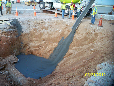
Figure 22: Placement of FCB around the plug in the manhole structure where the CMP entered the manhole.
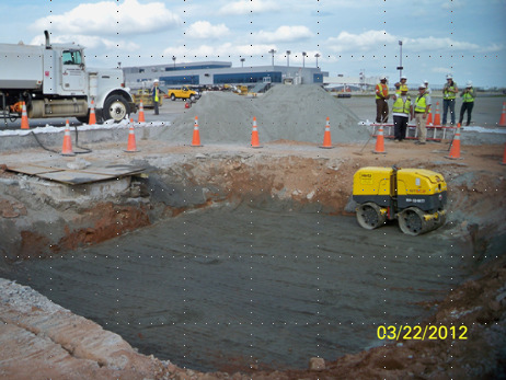
Figure 23: Compaction of M-10 sand above the flowable fill.
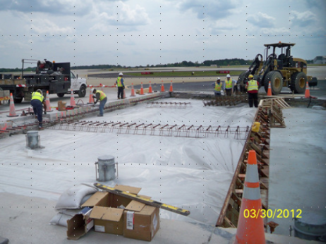
Figure 24: Repair area ready for placement of PCC.
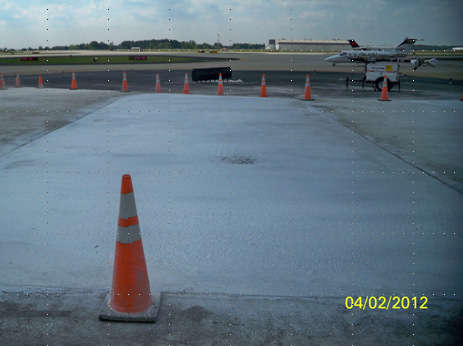
Figure 25: View of completed PCC pavement.
REFERENCES
Greer, W. C., Kuchikulla, S. R., and Drinkard, J. L., 2012. Pavement Management: Key to Sustainable Concrete Pavement at the World’s Busiest Airport. 10th International Conference on Concrete Pavements, Quebec City, Canada.
Greer, W. C., Kuchikulla, S. R., Masters, K., and Rone, J., 2013. Design, Construction, and Maintenance of Concrete Pavements at the World’s Busiest Airport. 9th International Conference on the Bearing Capacity of Roads, Railroads, and Airfields, Trondheim, Norway.